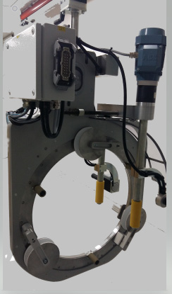
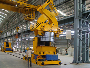
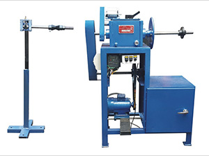
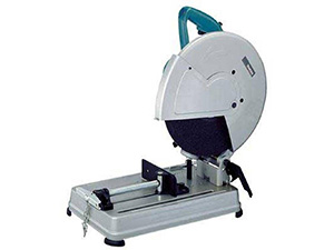
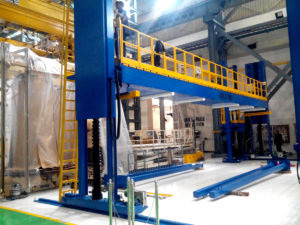
Asecond Tapping Machine
Machine Consists Winding Head with Elevation Mechanism. It is designed to tape up to 1600 MM Limb diameter & 4.5 Mt. Height. System is designed such a way that Opening to insert the machine is hold by machine itself & safer to use while placing on core.
Radio Remote facility is provided with the Machine to ease of Operation.
Machine comes with Trolley for Mobilization.
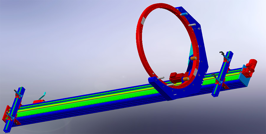
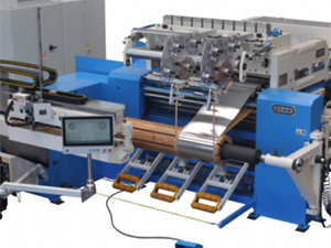
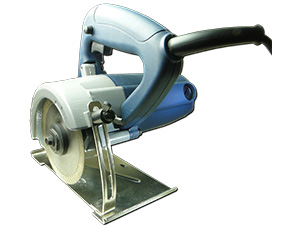
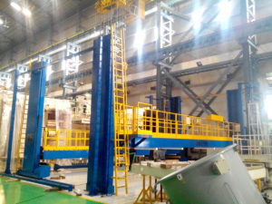
Tube Tapping Machine
The equipment is for the purpose of Taping your ref conductor using your specified crepe paper tape in spool form, using those tapes by Taping on conductor to required built up as per your specifications.
The machine is brief will consist following as below:
- Special Aluminium / M.S Powder coated section can be called as track with harden ground rod embedded/ fixed, for Taping head to travel.
- Taping head travelling unit.
- Job supporting resting jacks Total 4 Nos – one at fix end, other Three movable & up/ down by switch.
- Control unit/ Panel.
Oil Filtration System up to 25 KL
The Plant shall be suitable for treating Transformer & Switchgear oil by first heating it and then passing it through specially designed filter and then subjecting it to high vacuum treatment which dehydrates and degasifies the oil to following specifications after completion of the process.
| Parameters | After Processing |
|---|---|
| Break down Voltage ( Across 2.5 mm Gap ) | 80 KV |
| Moister Content | <3 to 5 PPM |
| Suspended Particles | 1 Micron |
| Gas Content | 0.1% of Volume |
| Acidity | 0.08 mg KOH/gms of Oil |
The Plant shall generally conform to IS:6034-1989 and its latest revision. The Oil Filtration Plant shall be designed for high vacuum and low temperature of oil for achieving required results. The Oil Filtration Plant shall be Mobile, mounted on an under carriage with Four Pneumatic wheels. Automatic brakes and towing arrangement shall be provided. The Plant shall be weather proofed and shall be suitable for outdoor use. The casing shall be provided with doors of CRCA Sheets, hinged on fabricated Framework, Angles and Channels to have access to the operational controls and inspection windows etc. The equipment shall be enclosed and protected against climatic conditions. The Screw Jacks for relieving pressure on wheels at stationary conditions, shall be provided. All components shall have adequate strength and rigidity to withstand normal conditions of handling transport and usage and shall be free from edges or corners to avoid injury to Operating Personnel in normal conditions of use.
The design of the Plant shall be such that if required the part/s can easily be replaced. Proper guarding arrangement shall be provided on all such parts which due to their position and nature of operation are liable to cause accidents.
The Plant shall consist of the following:
INLET PUMP
- A positive displacement gear type Pump with a capacity of 6000 LPH shall be provided. The Pump shall be thoroughly tested for vacuum and shall be suitable for continuous trouble free operation. The Pump shall be provided with automatic protection against over-pressure build-up.
- Interlocking arrangement shall be provided in between the Oil Inlet Pump and the heater so that heater can not be energised unless Inlet Pump is on. Interlocking arrangement shall be provided in the Filter Plant between the Inlet Pump and High Level Float Switch (located into Degassing Column) to avoid excessive rise of oil in the Degassing Column.
- Flow Control Valve for adjustment of flow rate through Filter, a Flow Control Valve shall be provided across the Gear Pump.
- The Suction Head of the Inlet Feed Pump at atmospheric condition at Inlet shall be 4 to 5 mtrs.
HEATERS
- Heaters shall be provided in Protection Tubes to avoid localised overheating, hot spot & breaking oil. Heaters shall be capable of heating oil from 30oC to 60oC. Temperature during degassing and dehydration for good results should not exceed 60oC. Heaters shall be thermostatically controlled. Total Heater Power shall be 132 KW. Heaters shall be divided into Three Groups.
- Heater Elements shall be of Nichrome / Kanthal wire filament, inserted in Refractory Formers which are located in Protection Tubes. Construction of the Heat Exchanger shall be such that the replacement of Heaters shall be easy and shall not require any special tools.
- Heaters shall be interlocked with Gear Pump and shall not be in ON position, unless the Inlet Pump is working. Heater Tank shall be adequately thermally insulated to minimise loss of heat.
- Heater Pipe surface density shall not be more than 2.0 Watts/cm2.
- Each group of Heaters shall be controlled by individual Thermostat. A Safety Thermostat shall be provided to take care of any accidental rise of temperature of oil and shall put off the Heaters in such eventuality. This Thermostat shall be set at slightly higher temperature than that of controlling Thermostats.
- One suitable Pressure Relief Valve shall be provided on the Heater Chamber to prevent any pressure rise above the acceptable limit. A Drain Plug for the Heater Tank shall be provided.
IONIC REACTION COLUMN (100 KGS)
An Ionic Reaction Column of 100 Kgs capacity shall be provided to reduce the acidity in the oil as mentioned in the specification. First filling shall be provided alongwith the column.
FILTRATION SYSTEM
Filtration System shall consist of the following:
- PRELIMINARY FILTER
The main function of this Filter shall be to prevent any damage to the Inlet Pump. It shall have strainers capable of retaining all particles above 1 mm size and also magnetic particles. Incoming oil shall pass through this Filter. It shall be possible to clean the strainer without dismantling the Filter from the pipeline. - FILTER PRESS
Filter Press shall consist of Filters held between Metallic Discs. Filters shall be easily changeable. It shall be suitable for removal of particles bigger than 50 Microns. This shall be useful for removal of sludge content in the used oil. A Drain Plug shall be provided for the Filter. - CARTRIDGE FILTER
Non-hygroscopic throw away type Cartridge Filters of one Micron rating shall be provided. This Cartridge Elements shall have large dust holding capacity. The replacement of Cartridge Elements is very easy and can be done without any special tools. The Housing / Vessel is suitable for high vacuum and pressure applications. Compound (Pressure / Vacuum) Gauge shall be provided on Filter Vessel for inlet pressure indication in order to ascertain condition of Cartridge Elements. Aeration shall be provided on the Filter Vessel to aerate the Vessel during draining. The Cartridge type Filter shall facilitate to achieve desired value of particle size in micron.
DEGASSING AND DEHYDRATION CHAMBER – TWO STAGE
The Degassing Chamber shall function as degasser and dehumidifier & shall be capable of removing dissolved gases and moisture from the oil. It shall be of M.S. and shall have welded construction. The Chamber shall be able to withstand the vacuum to which it shall be subjected. Efficiently spread Raschig Rings shall be placed in the Degassing Columns. The surface area offered by the Raschig Rings shall be sufficient to form a thin film of oil and shall facilitate removal of dissolved gases and moisture at the rated flow rate of oil. A Sight Glass with Illuminating Lamp shall be provided for observation of oil flow. One Float Switch on the Degassing Chamber shall be provided for preventing excess rise of level. It shall be electrically interlocked with Inlet Pump. Another Float Switch to control the low level of the oil in Degassing Chamber shall be provided and it shall be electrically interlocked with the Discharge Pump. Two stages shall be separated by a Siphon Seal.
VACUUM PUMPING SYSTEM (FOR DEGASSING COLUMN)
A Roots-Rotary combination of Vacuum Pumps shall be provided for evacuation of Degassing Chamber. The Pumps shall be of imported make. For matching of Vacuum Pump performance both – Roots & Rotary Vacuum Pumps shall be of same manufacturer only. Acceptable makes are Shinko Seiki, Japan / Balzer’s, Germany. Manufacturer’s specifications for the same are as given below:
- The Transformer Evacuation System shall be mounted on the Plant chassis.
- FIRST STAGE – ROTARY OIL SEALED PUMP (1 NO.)
Nominal Pumping Speed 3700 Ltrs/Min. Ultimate Vacuum with G.B. Closed 5 x 10⁻³ Torr, Ultimate Vacuum with G.B. Open 5 x 10⁻¹ Torr - SECOND STAGE – MECHANICAL BOOSTER PUMP (ROOTS PUMP) – 1 NO.
Nominal Pumping Speed 1200 M3/Hr, Ultimate Vacuum 10-4 Torr - The Vacuum Pumping System shall have a McLeod Vacuum Gauge (Range: 10 Torr to 10 Microns), a Bourdon Gauge (Range: 0 to 760 Torr), Isolation Valve, Airing Valve Mechanical Non Return Valve and Automatic bypass Valve for Roots Pump.
TRANSFORMER EVACUATION SYSTEM
A Roots-Rotary combination of Vacuum Pumps shall be provided for evacuation of the Transformer. The Pumps shall be of imported make. For matching of Vacuum pump performance both – Roots & Rotary Vacuum Pumps shall be of same manufacturer only. Acceptable makes are Shinko Seiki, Japan/ Balzer’s, Germany. Manufacturer’s specifications for the same are as given below:
- ROTARY OIL SEALED PUMP (1 NO.)
Nominal Pumping Speed 1500 Ltrs/Min. Ultimate Vacuum with G.B. Closed 5 x 10⁻³ Torr, Ultimate Vacuum with G.B. Open 5 x 10⁻¹ Torr - MECHANICAL BOOSTER PUMP (ROOTS PUMP) – 1 NO.
Nominal Pumping Speed 500 M3/Hr, Ultimate Vacuum 10-4 Torr - The Vacuum Pumping System shall have a McLeod Vacuum Gauge (Range: 10Torr to 10 Microns) and a Bourdon Gauge (Range: 0 to 760 Torr), Isolation Valve, Airing Valve Mechanical Non Return Valve and Automatic bypass Valve for Roots Pump.
DISCHARGE PUMP
- A Centrifugal Glandless type Discharge Pump with a capacity of 25000 LPH, suitable for sucking oil from the Degassing Chamber held under vacuum, shall be provided. This shall be fully tested for pressure and vacuum leak rate.
- Interlocking arrangement shall be provided between Low Level Float Switch (located in Degassing Column) and Discharge Pump to prevent dry running of Discharge Pump.
- The Discharge Head of the Outlet Pump shall be 8 Mtrs.
SOLENOID VALVE AT INLET & OUTLET
One no. Solenoid Valve at Inlet and One no. at Outlet shall be provided. Valve at the Inlet & Outlet shall open automatically. The moment oil Inlet & Outlet Pump are switched ON. In case of power failure, these valves shall be capable of preventing the oil from entering into the Plant and thus avoiding the possibility of mixing processed oil with unprocessed oil.
OIL SAMPLING VALVE
This valve shall be provided to collect the sample of oil for testing during operation.
AIRING VALVE
One Airing Valve for airing the Degassing Chamber shall be provided.
GAUGES & INSTRUMENTS
- A Dial type Thermometer shall be provided at Outlet & Inlet at the Heater Tank for indication of oil temperature.
- PRESSURE GAUGE
One Pressure Gauge before Cartridge Filter and One Compound Gauge shallbe provided near Degassing Column. - INDEPENDENT DRIVES
Independent Drives for Oil Discharge Pump, Oil Inlet Pump & Vacuum Pumps shall be provided. - Motors shall conform generally to IS:325 (Testing) shall be of Class ‘F’ Insulation. Starters shall be of direct On-line type. Motors shall be of NGEF / JYOTI (JMP) / ALSTOM / ABB / CROMPTON /SIEMENS make.
CONTROL PANEL
- All Electrical Control Gear, Mains Isolating Arrangement, Starters, Contactors,Pilot Lamp, Push Buttons, HRC Fuses, Relays, Indicating Lamps and Interlocking shall be housed in a Compact Control Panel and made of CRCA Sheets.
- A Mimic diagram with Indicating Lamps shall be provided on the Control Panel.
- All Wiring shall be neatly routed and all wire termination shall be suitably identified with ferrules.
- All HRC Fuses shall be of English Electric make and Switchgear shall be of Telemechanic / ABB /BCH / SIEMENS / L&T / GE POWER make. Mains Isolating Switch shall be of ICTPN type.
- The Plant shall be suitable for operation on 415 V, 3 Ph, 4 Wire, 50 Hz, A.C. Supply.
OIL HOSES – 2 NOS.
Two Nos. Nitrile Rubber Hoses each 10 Mtrs long with flanged end connection on both sides shall be provided. One for Oil Inlet & one for Oil Outlet. Oil Hoses shall be capable of handling the transformer oil at 100oC (max.) and vacuum.
PIPE LINE & VALVES
- The Valves in Oil Line & Vacuum Line shall be of Ball type. All Pipes shall be of ERW and all joints in Oil & Vacuum Line shall be flanged & shall have ‘O’ Ring Sealing. ‘O’ Rings shall be of Nitrile Rubber & shall be of round shape.
- The entire Plant along with all components mounted shall be tested for a total vacuum leak rate of less than 1 torr Ltrs/Sec
The supplier should confirm availability of testing facilities at their works for carrying out the following tests on the oil:
- Break Down Voltage
- Moisture Content
- Suspended Particles
- Gas Content
- Acidity
- Plant flow rate confirmation
LIFTING HOOKS
Lifting Hooks for Plant shall be provided to facilitate ease of Plant Loading /Unloading.
ADDITIONAL REQUIREMENTS
- Additional one Vacuum pump of same capacity for evacuation of transformer.
- Online PPM Measurement.
- BDV Test kit upto 100kV.
OTHER DETAILS
- CLEANING & PAINTING
Before despatch from Supplier’s works, all exposed surfaces shall be cleaned off Rust, Dirt, Scale and foreign matter and shall be applied with a coat of rust preventive compound before being painted in single paint from outside. - INSPECTION & TESTING
The Plant shall be offered for Inspection & Testing with Transformer Oil at Supplier’s works. Supplier shall demonstrate the Plant performance as per parameters mentioned in the specifications. - INSTRUCTION MANUAL
Two copies Instruction Manual containing details of Plant Operation & Maintenance alongwith all relevant drawings shall be supplied with the Plant. - COMMISSIONING
Vendor shall depute their Engineer to our site for commissioning of the Plant. The oil to be processed and the Electrical Supply will be kept ready at site by BHEL. - PERFORMANCE GUARANTEE
We give guarantee for performance of the Plant for a period of 12 months from the date of commissioning of the Plant or 18 months from the date of despatch, whichever is earlier. During guarantee period we undertake upon written request of the purchaser to repair or replace at our discretion & as soon as possible any parts of goods delivered which can be proved to be damaged or unfit due to bad material, faulty design or poor workmanship. - This guarantee does not cover damages resulting out of normal wear & tear, improper maintenance, failure to observe the operating instructions, incorrect operation, excessive loading, the use of unsuitable material, & other reasons beyond our control. The guarantee does not cover Consumables, Rubber parts (including Oil/Vacuum Hoses) & Electrical Components-Motors.
Pressure Roller System for Winding
The Main Purpose to Pressure roller system is to optimize the winding of Bending Copper. It deals with the system of two roller system one is Horizontal & Other is Vertical by compression of Pneumatic pressure & Braking. This aim warrants obtaining a perfect alignment of bending copper with safety for the Operators & it permits to economize man hours.
Advantage
- Winding Space Optimization
- Uniformity of the Coil
- Safety
- Improved Performance
Evacuation System Single Stage & Double Stage Vacuum Facility.
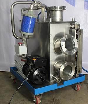
System evacuates the gases, water Vapour from the Transformer to achieve vacuum insulation & Dry the Active part from the Moist to enhance the Insulation property to achieve the High-Power Performance. System is Equipped with,
Vacuum Pump
Dual-stage, high-performance rotary vane pump with Single-phase Motor Integrated gas ballast and HV safety valve for all low and medium vacuum applications Magnetically coupled.
Vapour Trap Chamber
SS 316 Material Used to ensure the Dust & Contamination free atmosphere for Transformer Assembly. Equipped with Option of Flexible Coupling to ensure the connection of well enough Instruments for monitoring the system. i.e., Isolation Valve, Claw Clamp for Inlet Hose Connection, Volume is selected such a way to ensure the tripping of the system before the entrapment of Liquid in Pump. So, Pump can be performed long life Operation without Breakdown. Level Indicator & Inspection Sight Glass are also providing to view actual condition of Trap in case of Electrical/ Electronic Interlock is not working. Tank can be cleaned by Hand after opening the Inspection Sight Glass. It is designed intentionally of large size to ensure the hand access. Last but not the least Draining facility provided with Proper Slope at Bottom of the Tank to complete drain of Trap.
Portable Trolley
Equipped with Free Moving Skates to ensure movement by Single handed & Braking also available.
Flexible Connection
To Ensure the Flexibility to connect with different possibilities without changing the parent equipment accessories.
Electrical Controls & Accessories
Cable Reel with Operating Panel provided to ensure the proper wrap up to enhance the Cable Life & Safety of the equipment. Evacuation Systems are available in various technical versions depending on the specific requirements. AEPL offers a wide range of possible combinations and a great degree of flexibility at all times.
Mandrel/Former with Torque Limiter Mechanism.
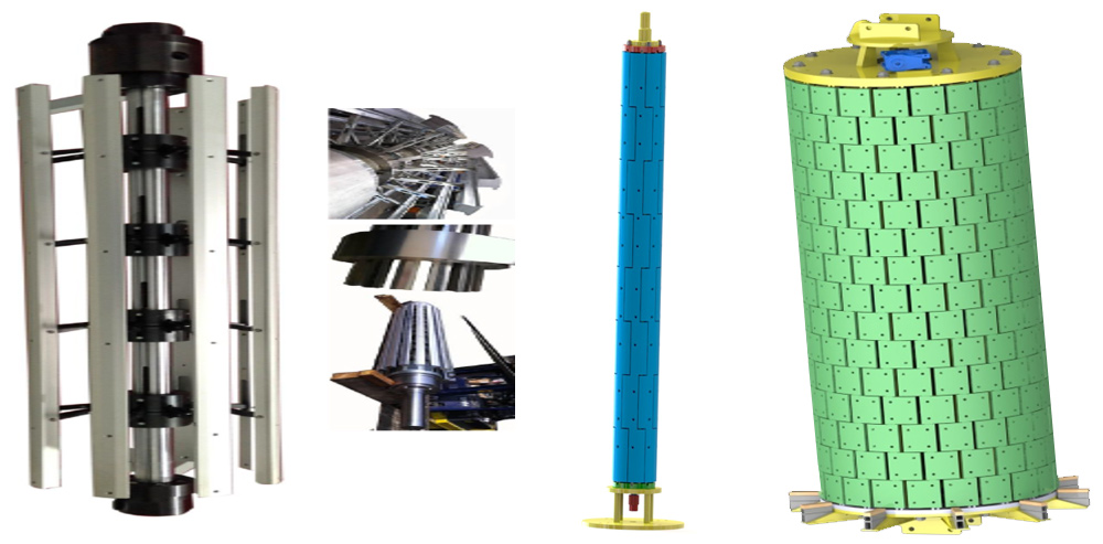
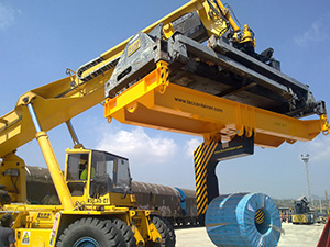
Coil Lifting Structure
CTC Bobbin Stand with Pneumatic Breaking & Motorized Drive
Tension Device for Horizontal Winding Machine/Vertical Winding Machine Pit Type

Bending Tool
Various Tools to perform Bending in various shape as per requirement, It can be operated by Electro Hydraulic , Pneumatic Hydraulic or Manual.

Cutting Tool

Coil Preparation Table
Active Part Station
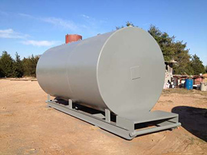
Oil Tank up to 50KL